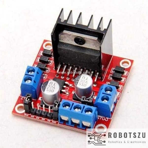
This makes it ideal for robotic projects, as most robots have either two or four powered wheels. The L298N actually contains two complete H-Bridge circuits, so it is capable of driving a pair of DC motors. The L298N can handle up to 3 amperes at 35 Volts DC, which is suitable for most hobby motors.

The difference between the family members is in the amount of current they can handle. The L298N is a member of a family of IC’s that all have the designation “L298”. This causes change in spinning direction of the motor. Closing two particular switches at the same time reverses the polarity of the voltage applied to the motor. An H-Bridge circuit contains four switches with the motor at the centre forming an H-like arrangement. A common technique for doing this is to use an H-Bridge. The DC motor’s spinning direction can be controlled by changing polarity of its input voltage. H-Bridge – For controlling rotation direction The higher the duty cycle, the greater the average voltage being applied to the dc motor(High Speed) and the lower the duty cycle, the less the average voltage being applied to the dc motor(Low Speed).

A common technique for doing this is to use PWM (Pulse Width Modulation) PWM is a technique where average value of the input voltage is adjusted by sending a series of ON-OFF pulses. The speed of a DC motor can be controlled by varying its input voltage. DC Motor Controlling can be achieved by combining these two techniques. In order to have a complete control over DC motor, we have to control its Speed and Rotation Direction.


Coupling the L298N H-Bridge to a microcontroller like an Arduino Uno, ESP32 board will give you the ability to control both the speed and rotation direction of two DC motors. The L298N H-Bridge module is a simple way to achieve that. In this tutorial, we will learn How to control DC motor with ESP32 using L298N-Bridge Motor driver ?.


 0 kommentar(er)
